

Views: 288 Author: Site Editor Publish Time: 2026-07-23 Origin: Site
Scaling from mid-volume to high-volume manufacturing presents a severe operational challenge. You cannot simply multiply floorspace, labor, and cycle times linearly and expect to remain profitable. Manufacturers inevitably hit a breaking point where relying on conventional multi-axis CNC cells becomes inefficient and physically impossible. Evaluating a Horizontal Rotary Transfer Machine emerges as a powerful strategic alternative to deploying rows of linear CNCs for true mass production.
By machining multiple sides of a stationary workpiece simultaneously, these systems fundamentally alter throughput dynamics. This guide breaks down the core operational realities, critical investment thresholds, and technical evaluation criteria required for confident procurement decisions. You will learn how to identify existing bottlenecks, mitigate adoption risks, and objectively assess if this technology fits your demanding production floor.
Volume Threshold: Horizontal rotary transfer machines are typically justified when annual part volumes exceed 500,000 units, significantly reducing cost-per-part.
"Hands-Off" Efficiency: Simultaneous multi-station machining limits work-in-progress (WIP) and reduces human intervention compared to cell-based CNC routing.
Evaluation Priority: Vendor selection must heavily weigh tooling flexibility, CNC changeover times, and part-family compatibility alongside baseline cycle time.
Risk Mitigation: High initial CAPEX requires rigorous pre-purchase time studies and a realistic assessment of in-house maintenance capabilities.
Recognizing the right moment to abandon traditional cellular manufacturing requires careful observation. Sequential multi-axis CNC lathes or mills eventually fail to meet aggressive cycle time requirements. When you push standard equipment past spatial constraints, inefficiencies multiply rapidly. You start noticing severe bottlenecks on the shop floor. Operators constantly move parts between disparate stations, increasing the risk of mishandling and stacking up massive amounts of work-in-progress (WIP).
Addressing severe labor shortages requires decisive action. The "hands-off" production mandate forces competitive shops to consolidate operations. You can combine turning, milling, drilling, and threading into a single, automated, unattended enclosure. This consolidation dramatically limits human error. A part enters as raw stock and exits completely finished. You eliminate queue times between secondary operations entirely.
Determining if your specific part-family mix warrants a dedicated transfer system relies on a clear volume versus flexibility framework. Consider the following tipping points:
The 500,000 Unit Mark: Once a single part or closely related part family crosses half a million units annually, standard flexible machining centers become mathematically inefficient.
Cycle Time Walls: If your current cycle time hovers at 45 seconds on a twin-spindle lathe, but your contract demands 10 seconds, sequential machining will never bridge the gap.
Labor Availability: Running three shifts across six standard CNCs requires up to eighteen operators. A single transfer system requires only one or two highly skilled technicians per day.
You must weigh these factors objectively. A highly flexible 5-axis mill serves low-volume, high-mix environments perfectly. However, it fails completely when tasked with producing millions of automotive fluid fittings or brass gas valves year over year.
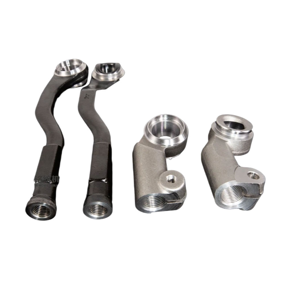
Engineers categorize these automated systems based on spindle architecture and control mechanisms. Horizontal spindle configurations dominate the market for several distinct reasons. First, they provide superior chip evacuation. Gravity naturally pulls metal swarf away from the cutting zone. This prevents chips from re-cutting, which saves tool life and protects surface finishes. Second, horizontal designs accommodate continuous bar stock feeding much more effectively than vertical alternatives. Finally, horizontal layouts allow exceptional access for complex cross-machining on multiple axes.
When selecting a core configuration, buyers typically choose between mechanical and full-CNC architectures. Each serves a distinct production philosophy.
Feature | Mechanical (Cam-Driven) | Full CNC Architecture |
|---|---|---|
Primary Use Case | Static, ultra-high-volume parts | Families of parts, moderate-to-high volume |
Speed & Throughput | Maximum possible speed (fractions of a second) | Slightly slower, but highly optimized |
Flexibility | Extremely low (fixed tooling paths) | High (programmable axes, software adjustments) |
Changeover Time | Often takes days to re-cam | Hours (via program offsets and modular tooling) |
Mechanical cam-driven units operate at blinding speeds. They lock into a specific rhythm, making them ideal for manufacturing identical ammunition casings or simple plumbing fittings for a decade. Conversely, full CNC models introduce programmable axes. They offer faster changeovers. You can adjust tool offsets digitally rather than physically grinding mechanical cams.
Workholding variations also dictate machine design. Collet systems serve bar stock applications perfectly. They grip extruded metals securely for high-speed indexing. However, if you machine near-net-shape castings or raw forgings, you require custom indexing chucks. These specialized chucks orient irregularly shaped blanks precisely before the first tool ever touches the metal.
Procuring a massive automated asset requires stringent technical evaluation. You must look far beyond the initial brochure specifications. Cycle time and station optimization serve as your primary evaluation metrics. In rotary transfer machining, the longest single operation dictates the entire machine's heartbeat. We call this the limiting factor.
If drilling a deep central hole takes 15 seconds, but threading takes 3 seconds, the table can only index every 15 seconds. Top-tier vendors solve this by splitting operations. They divide that deep hole across three separate stations (e.g., pilot drill, half-depth drill, final depth drill). This reduces the limiting factor to just 5 seconds. Evaluating how vendors distribute operations across 12 to 16 stations separates excellent engineering from mediocre proposals.
Next, calculate your floorspace to output ratio. Factory floor real estate remains incredibly expensive. Measure the anticipated revenue output per square meter. Compare the footprint of a single Horizontal Rotary Transfer Machine against the sprawling layout required for 4 to 6 standalone CNC lathes, including the space needed for robots, conveyors, and safety fencing.
Tooling and material compatibility also dictate machine construction. Machining tough alloys like stainless steel or aerospace titanium demands immense structural rigidity. You must look for cast iron beds and high-torque, gear-driven spindles to prevent chatter. Conversely, cutting free-machining brass or aluminum prioritizes speed. You need high-speed direct-drive spindles capable of reaching 20,000 RPM instantly.
Finally, evaluate post-process compliance and integration. The machine cannot function as an isolated island. It must integrate seamlessly. Assess the mechanisms for automated part unloading. Scrutinize the post-process washing systems. Furthermore, demand robust data connectivity. Modern factory managers require Industry 4.0 integration to track Overall Equipment Effectiveness (OEE) and tool wear in real-time.
Embracing advanced manufacturing automation introduces formidable challenges. Buyers must navigate specific implementation realities before signing purchase orders. The changeover challenge catches many new adopters off guard. While modern CNC transfer machines offer incredible flexibility compared to their cam-driven ancestors, setup times still dwarf those of standard equipment. Transitioning an entirely new part might require swapping chuck jaws, changing dozens of cutting tools, re-aligning coolant nozzles, and running slow-motion prove-outs. This process can consume an entire production shift.
High initial CAPEX represents the most obvious barrier. You must balance a $1M+ upfront capital investment against long-term operational gains. The justification relies entirely on drastic cost-per-part reductions. You offset the massive sticker price by virtually eliminating direct labor overhead and drastically reducing scrap rates over a five-to-ten-year horizon.
Underestimating the complexity of programming overlapping toolpaths.
Failing to upgrade raw material quality (inconsistent stock jams automated loaders).
Assuming standard lathe operators can immediately run multi-station systems without formal training.
Skill gaps and maintenance pose severe risks. Operating a 16-station system requires specialized operator training. Technicians must understand multi-station troubleshooting. If a thermal alarm triggers at station 7, the operator must know how it affects the indexing table synchronization. Preventative maintenance becomes uncompromising. If the central indexing table loses accuracy, every single part produced becomes scrap.
Tool management complexities also scale exponentially. You must manage tool life across 20 or more simultaneous spindles. A broken drill at station 4 will destroy the tap at station 5. To prevent catastrophic cascading failures during unattended shifts, you must invest heavily in laser tool breakage sensors and spindle load monitors. These systems stop the machine instantly the moment a tool deviates from its expected power consumption.
Selecting the right OEM partner requires a methodical, evidence-based approach. Never begin vendor discussions by asking for a generic price quote. The required first step is requesting a detailed time study. Send your part drawings, material specifications, and annual volume requirements to prospective builders. They must return a preliminary tool layout and a guaranteed cycle time. This document proves they understand your specific machining challenges.
Evaluate vendors based on their integration capabilities. Decide early between a turnkey integration or standard delivery. You want an OEM capable of providing fully runoff, turnkey solutions. This means they build the machine, integrate the bar feeders, set up the robotic unloaders, and prove the entire process on their factory floor before shipping it to yours.
Proving the ultimate ROI relies on rigorous cost-per-part analysis. Structure a comprehensive financial model. You must factor in the expected machine life, projected tooling consumption, and measurable scrap rate reduction. Account for labor reallocation—moving operators from mundane loading tasks to higher-value quality control roles. Do not rely on gut feelings; let the math dictate the final decision.
A horizontal rotary transfer machine does not function as a general-purpose tool. It exists as a highly targeted, uncompromising engine designed specifically for mass production. When deployed correctly, it obliterates standard cycle times, eliminates labor bottlenecks, and maximizes output per square meter of factory floor. However, the high capital requirement and technical complexity demand profound respect.
Move forward confidently only if your part volume mathematically guarantees high utilization. Demand that your chosen vendor contractually guarantees both cycle times and CPK (statistical process capability) during the final factory runoff. By doing so, you protect your investment and secure a dominant competitive advantage in high-volume manufacturing.
Audit your current shop floor to identify multi-machine bottlenecks handling over 500,000 units annually.
Compile 3D CAD models and material specs for your highest-volume part families to prepare for OEM time studies.
Assess your internal maintenance bandwidth to ensure you can support complex indexing and multi-spindle preventative maintenance.
A: The threshold typically ranges from 500,000 to over 1,000,000 parts annually. However, modern full-CNC models can often justify volumes as low as 250,000 if the production is divided among a very similar part family that shares tooling setups.
A: In a rotary transfer machine, the workpiece generally remains stationary while it indexes from station to station, and the cutting tools rotate. In contrast, a multi-spindle lathe rapidly spins the actual workpieces into stationary cutting tools.
A: Yes. They handle tough alloys easily, provided the machine bed offers sufficient cast-iron rigidity. The specific cutting stations must also be equipped with high-torque, gear-driven spindles rather than just relying on high-speed direct drives meant for aluminum.
A: Changeovers typically vary from 2 to 8 hours. The exact time depends heavily on the scope. Minor dimensional adjustments within an existing part family take minimal time, whereas a complete chuck, collet, and tooling swap takes significantly longer.


