

Views: 0 Author: Site Editor Publish Time: 2026-09-16 Origin: Site
High-volume production environments demand ruthless efficiency. Manufacturers constantly battle process bottlenecks. You face tolerance stacking and excessive labor costs daily. Relying on sequential CNC operations across multiple standalone machines often cripples throughput. Every manual part transfer wastes valuable cycle time. A rotary transfer system completely eliminates this workflow lag. It consolidates sequential processes into a single, simultaneous multi-station cycle. Parts index around a central table. They undergo multiple cutting operations concurrently.
This guide explores the diverse capabilities of these robust systems. We help production managers evaluate operational strengths. You will learn to compare different machine architectures. We will also help you determine if this technology justifies the capital expenditure for your specific part families.
RTMs can perform a comprehensive suite of operations—including drilling, milling, tapping, turning, and broaching—simultaneously on a single workpiece.
Selecting between a Vertical Rotary Transfer Machine and a Horizontal Rotary Transfer Machine depends heavily on part geometry, chip evacuation requirements, and floor space constraints.
Purpose-built configurations, such as a Gate Valve Rotary Transfer Machine or a Manifold Rotary Transfer Machine, drastically reduce cycle times for complex, multi-axis fluid control components.
The primary evaluation metric for RTM adoption is production volume; the high initial CapEx is typically justified when annual part volumes exceed 100,000–250,000 units.
Modern transfer systems act like an entire factory floor packed into a single footprint. They execute dozens of unique cuts in seconds. This happens because multiple tool spindles engage the workpiece simultaneously. Operators do not need to move parts between different milling and turning centers. We can categorize these core capabilities into five distinct machining groups.
Deep hole drilling and precision boring happen efficiently at dedicated stations. Spindles advance radially or axially toward the clamped part. You achieve precise internal diameters effortlessly. Reaming stations follow the drilling stations immediately. They ensure superior surface finishes in a single index. The machine clears chips rapidly between indexing steps. This prevents tool breakage and ensures consistent bore geometries.
Creating threads often slows down traditional CNC cycles. Transfer systems handle this seamlessly. They utilize high-speed rigid tapping for internal threads. They also deploy single-point threading tools for external connections. Threading heads synchronize perfectly with the spindle rotation. You finish internal and external connections without secondary handling. This eliminates the risk of cross-threading during manual re-fixturing.
Complex parts require slots, flats, and external profiles. Multi-axis milling heads execute these features effortlessly. One station might machine a complex hexagonal flat. The adjacent station simultaneously handles internal boring features. Operators can program complex interpolations using standard CNC codes. This allows for intricate contouring alongside heavy stock removal.
Turning typically requires a spinning workpiece. However, asymmetrical castings cannot spin at high speeds safely. Transfer systems solve this elegantly. They utilize rotating tools and specialized contouring heads. These heads perform turning operations on stationary parts. The cutting tool spins around the clamped component. It feeds inward to cut grooves, chamfers, or external profiles. Specific chucking configurations also allow part rotation if needed.
Engineers often integrate unique operations directly into the cycle. You can add broaching stations for internal keyways. Cross-drilling modules create intersecting fluid passages. Many manufacturers even integrate automated marking tools. You can laser-etch serial numbers before the part drops into the bin. Some modern configurations incorporate automated inspection. Gauging probes verify critical dimensions before releasing the part.
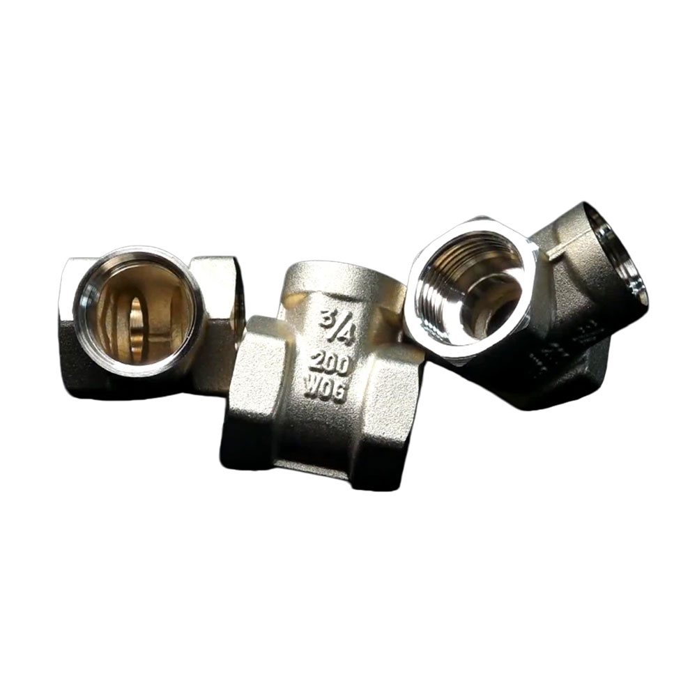
Choosing the right machine architecture determines your production success. The orientation of the indexing axis dictates how the machine handles chips, gravity, and tooling access. You must match the architecture to your specific part geometry. Floor space availability also plays a crucial role in this decision.
The indexing table rotates on a horizontal axis in this configuration. The spindles typically approach the part horizontally. This layout is best suited for longer, cylindrical parts. It excels when machining shafts or components requiring bar-fed stock. You feed a long metal bar through the central trunnion. The machine cuts, machines, and separates the part automatically.
A Horizontal Rotary Transfer Machine offers exceptional chip control. Gravity pulls the metal chips straight down into a centralized conveyor. They naturally fall away from the cutting zone. This natural gravity-assisted chip evacuation prevents recutting. It extends tool life significantly when machining sticky materials like aluminum.
The indexing table rotates on a vertical axis here. The clamping fixtures sit flat on a large rotary dial. The cutting tools approach from the top, sides, or bottom. This layout is ideal for forged, cast, or pre-cut blanks. It handles bulky items requiring multi-sided machining. Operators usually load discrete blanks manually or via a robotic arm.
A Vertical Rotary Transfer Machine requires a much smaller factory footprint. The machine base is extremely heavy and rigid. This highly rigid base structure absorbs massive vibrations. It is perfectly suited for heavy-duty cutting on complex geometries like cast iron valve bodies.
Architecture Comparison: Vertical vs. Horizontal
Feature/Metric | Horizontal Architecture | Vertical Architecture |
|---|---|---|
Primary Stock Material | Long bar stock, extrusions, shafts | Forgings, castings, pre-cut billets |
Chip Evacuation | Excellent (Gravity pulls chips downward) | Moderate (Requires high-pressure coolant wash) |
Factory Footprint | Large (Requires space for bar feeders) | Compact (Circular vertical layout saves space) |
Base Rigidity | High | Extremely High (Ideal for heavy milling) |
Certain industries demand massive volumes of highly complex parts. These sectors benefit the most from specialized transfer technology. Standard machine tools simply cannot match the output speeds required by global supply chains. Let us examine three key sectors driving this technological adoption.
Valve manufacturing involves cutting multiple intersecting bores. Flanges require precise facing. Internal seats demand accurate contouring to prevent leaks. Moving a valve body between multiple lathes and mills invites disaster. Every new clamping setup introduces tolerance stacking. You lose microscopic accuracy during each transfer.
Deploying a purpose-built Gate Valve Rotary Transfer Machine solves this completely. It allows for simultaneous machining of all intersecting bores. Flange facing and precise seat contouring happen without un-clamping the part. This "done-in-one" approach eliminates tolerance stacking entirely. You achieve superior sealing surfaces and drastically reduce scrap rates.
Hydraulic control blocks present a unique manufacturing nightmare. They contain dozens of intersecting cross-holes. They require complex porting and deep threading. A traditional horizontal machining center (HMC) struggles here. The HMC must constantly stop cutting to change tools. A single manifold might require forty distinct tool changes. This wastes immense amounts of time.
A dedicated Manifold Rotary Transfer Machine excels at executing these features. It houses dedicated spindles for every single drill, tap, and mill. The machine performs dozens of operations in a single rotation. It drastically reduces the cycle time compared to traditional HMCs. What takes an HMC ten minutes might take this machine twenty seconds.
Automotive suppliers produce millions of identical components annually. They manufacture steering components, structural fittings, and sensor housings. These parts demand stringent repeatability standards. Airbag sensor housings require microscopic tolerances. Transfer systems deliver this consistency across millions of cycles. The aerospace sector uses them for high-volume fasteners and fluid connectors. The rigid setup ensures exotic metals meet strict aviation standards consistently.
Purchasing multi-station equipment requires careful financial justification. This equipment represents a major capital investment. It is not suitable for every machine shop. You must analyze your production metrics rigorously. The decision usually hinges on three distinct business factors.
Production volume dictates the entire business case. Standard CNC machines offer flexibility. They excel in high-mix, low-volume environments. Transfer systems dominate low-mix, high-volume production. You must analyze the crossover point carefully. The cost-per-part savings must outweigh the flexibility of standalone machines.
Industry consensus places this threshold high. You typically justify the investment when annual part volumes exceed 100,000 units. For highly complex parts, a threshold of 250,000 units makes the ROI undeniable. The machine pays for itself by slashing cycle times from minutes to mere seconds.
Labor shortages plague the manufacturing sector globally. Finding skilled machinists is increasingly difficult. A traditional setup requires 4 to 8 standalone CNC machines to match one transfer system. Each standalone machine requires an operator, or at least a dedicated robot cell.
Calculating the financial impact of consolidation is eye-opening. You replace several standalone CNC machines with a single automated cell. One trained operator manages the entire process. You eliminate multiple salaries, benefits, and training costs. Furthermore, you reclaim massive amounts of valuable factory floor space. This footprint consolidation lets you scale operations without building new facilities.
Every time an operator handles a part, risk increases. Re-fixturing introduces minute alignment errors. These errors compound across multiple machines. You end up with a high percentage of scrapped parts.
Transfer systems champion "done-in-one" processing. The part remains clamped in a rigid fixture throughout the entire cycle. This eliminates handling errors caused by re-fixturing. It also reduces work-in-progress (WIP) inventory significantly. You do not have bins of half-finished parts cluttering the shop floor. Raw material enters one side, and a finished, inspectable part exits the other.
Transitioning to multi-station processing involves technical and financial hurdles. Buyers must enter the procurement process with clear eyes. Miscalculating cycle times or ignoring maintenance needs can turn a profitable investment into a liability. We must address these implementation realities openly.
These machines carry high upfront costs. A fully tooled system often costs millions of dollars. You must address this reality through accurate financial modeling. Do not rely on rough estimates. You must demand accurate time-studies from vendors before procurement.
Vendors will simulate the machining cycle based on your specific part prints. They guarantee a specific cycle time. You use this guaranteed time to calculate your cost-per-part. A well-planned project usually achieves a payback period of 18 to 36 months. High volumes ensure rapid capital recovery.
Legacy cam-driven machines suffered from a terrible reputation. They had notoriously long setups. Changing a part family could take operators several days. You had to physically swap mechanical cams and rebuild gear trains. This made them strictly single-purpose machines.
Modern CNC variants mitigate this limitation entirely. They replace mechanical cams with modular tooling and servo-driven indexing. Operators load new part programs from the central console. Quick-change preset tooling allows rapid physical swaps. A skilled team can execute a complete changeover in just a few hours. This adds necessary flexibility for slightly lower-volume runs.
Operating these systems requires specialized knowledge. A standard lathe operator needs extensive training to manage a 16-station system. The necessity for specialized operator training is absolute. You must invest in your workforce.
Furthermore, machine downtime is brutally expensive. If one spindle fails, the entire 16-station machine stops. You lose the output of an entire factory cell. Rigorous preventative maintenance schedules are mandatory. You cannot run these machines until they break. Predictive maintenance prevents costly multi-station downtime. Proper lubrication, tool wear monitoring, and spindle vibration analysis ensure continuous profitability.
A multi-station transfer system radically transforms manufacturing economics. It is not a universal solution for every job shop. It is a targeted investment for eliminating secondary operations in high-volume, complex part production. By consolidating drilling, milling, and turning into one cycle, you eliminate WIP and slash labor requirements.
Buyers should prioritize vendors carefully. Shortlist partners who can provide rigorous pre-sale time studies. Verify their proven spindle reliability in harsh environments. Ensure they offer robust local service networks to support preventative maintenance. You cannot afford extended downtime waiting for overseas technicians.
Your next steps involve gathering your most challenging, high-volume part prints. Contact engineering partners to request a comprehensive cycle-time analysis. Ask for an ROI projection based on your specific annual volume requirements. This data will clearly indicate whether migrating to a transfer system is your most profitable path forward.
A: Cycle times are dictated by the longest single operation at any one station. Because dozens of tools cut simultaneously, the overall processing time often drops drastically. Manufacturers typically see reductions from several minutes on standard CNCs to just seconds per part.
A: Yes, they certainly can. Success requires appropriate spindle rigidity and high-pressure coolant delivery. The heavy cast iron bases absorb cutting vibrations easily. However, tool wear tracking becomes a critical metric when machining tough alloys at high speeds.
A: Unlike legacy mechanical machines that took days to reconfigure, modern CNC variants are highly agile. They utilize quick-change preset tooling, servo motors, and stored part programs. This technology reduces changeovers to just a few hours, increasing overall machine utilization.
A: These machines are extremely precise. They are capable of holding tight tolerances, often in the low microns. This high precision occurs because the part remains securely clamped in a single fixture—either a pallet or a chuck—throughout all machining operations.


