

Views: 0 Author: Site Editor Publish Time: 2026-09-23 Origin: Site
High-volume valve manufacturing faces a constant, unforgiving conflict. You must maintain strict geometric tolerances for concentricity, surface finish, and bore alignment. Simultaneously, you need to slash cycle times to meet aggressive production quotas. Conventional serial CNC machining often fails to deliver on both fronts. Moving parts between multiple setups introduces unavoidable tolerance stack-up. This serial approach simply cannot match the precision of simultaneous multi-station methods. A single-clamping strategy fundamentally transforms your factory floor. It eliminates setup-to-setup variance and locks in structural integrity from start to finish. This article gives engineering and procurement leaders a clear, objective framework. We will explore how to evaluate rotary transfer equipment effectively. You will learn about advanced tolerance capabilities, specific application fits, and rigorous implementation strategies. You can use these insights to make confident, data-driven decisions for your next major machinery upgrade.
Tolerance Integrity: Single-clamping processes eliminate setup-to-setup variance, making true position and concentricity highly repeatable.
Application Matching: Different architectures (horizontal vs. vertical) dictate success depending on valve type (gate, manifold, custom liquid-cooling bodies).
Production Volume Threshold: High initial tooling and setup costs require verifiable production volume floors (typically 100k+ parts/year) to justify ROI.
Risk Management: Successful implementation hinges on rigorous vendor runoff testing and thermal stability controls.
Valve body manufacturing hits a severe bottleneck when handling complex intersecting axes. Standard 4-axis or 5-axis mills process one part at a time. Operators must move parts between multiple setups. This serial process invites disaster on the production floor. Every re-clamping step introduces microscopic location errors. These errors stack up quickly across multiple operations. They create massive inspection bottlenecks. Scrap rates skyrocket when tolerances drift out of specification. Financial losses pile up fast when expensive forgings end up in the scrap bin.
The single-clamping advantage changes everything. You secure the raw forging or casting exactly once. A Rotary Transfer Machine handles the rest seamlessly. The machine completes turning, milling, drilling, and threading in one continuous chucking. You remove cumulative location errors entirely. True position values stabilize immediately. Concentricity across opposing bores becomes highly predictable. This approach ensures perfect alignment between critical fluid passageways.
Adoption requires strict baseline metrics. You must establish clear success criteria before purchasing equipment. Benchmark your expected Overall Equipment Effectiveness (OEE). High-performing automated lines target an OEE above 85%. Statistical process control (SPC) remains vital for long-term success. You need a Cpk and Cp requirement of 1.67 or higher. This guarantees six-sigma level quality for critical sealing surfaces. It proves your manufacturing process remains fully capable and in control.
Metric | Standard CNC Baseline | Transfer Machine Target | Impact on Valve Quality |
|---|---|---|---|
OEE (Effectiveness) | 60% - 70% | 85% - 95% | Maximizes machine uptime and output. |
Cpk (Process Capability) | 1.00 - 1.33 | > 1.67 | Ensures six-sigma reliability on seals. |
Scrap Rate | 3% - 5% | < 0.5% | Reduces wasted materials significantly. |
Setup Variance | High (Multiple clamps) | Zero (Single clamp) | Locks in concentricity automatically. |
Mechanical rigidity guarantees indexing precision. Hirth couplings provide exceptional mechanical locking mechanisms. They lock rotating stations into place securely. This delivers sub-micron repeatability during rapid table indexing. Direct-drive rotary tables offer another high-precision alternative. They use high-torque motors to position parts flawlessly. These rigid mechanical foundations prevent vibrations from reaching the cutting tool. You achieve superior surface finishes on critical valve seats.
Thermal stability dictates long-term accuracy. Continuous high-speed machining generates extreme heat. Thermal expansion easily ruins tight dimensional clearances. High-pressure coolant delivery prevents this dangerous tolerance drift. Targeted coolant nozzles flush hot chips away instantly. They keep the cutting tool and workpiece thermally neutral. Liquid cooling valve applications demand this strict level of thermal control. Consistent temperatures ensure your first part matches your thousandth part perfectly.
Simultaneous machining dynamics require careful balance. Heavy stock removal causes parts to deflect under heavy cutting pressure. Opposing spindles solve this physical problem perfectly. They engage the part simultaneously from both sides. This neutralizes mechanical cutting stress on the valve body. You maintain strict geometric alignment effortlessly. The balanced forces prevent the raw casting from warping during aggressive machining passes.
Best Practices for Maintaining Tolerances:
Implement strict ambient temperature controls around the machining cell.
Monitor coolant concentration and chilling systems hourly.
Schedule routine calibration for all Hirth coupling indexing mechanisms.
Replace cutting inserts before they show visible signs of excessive wear.
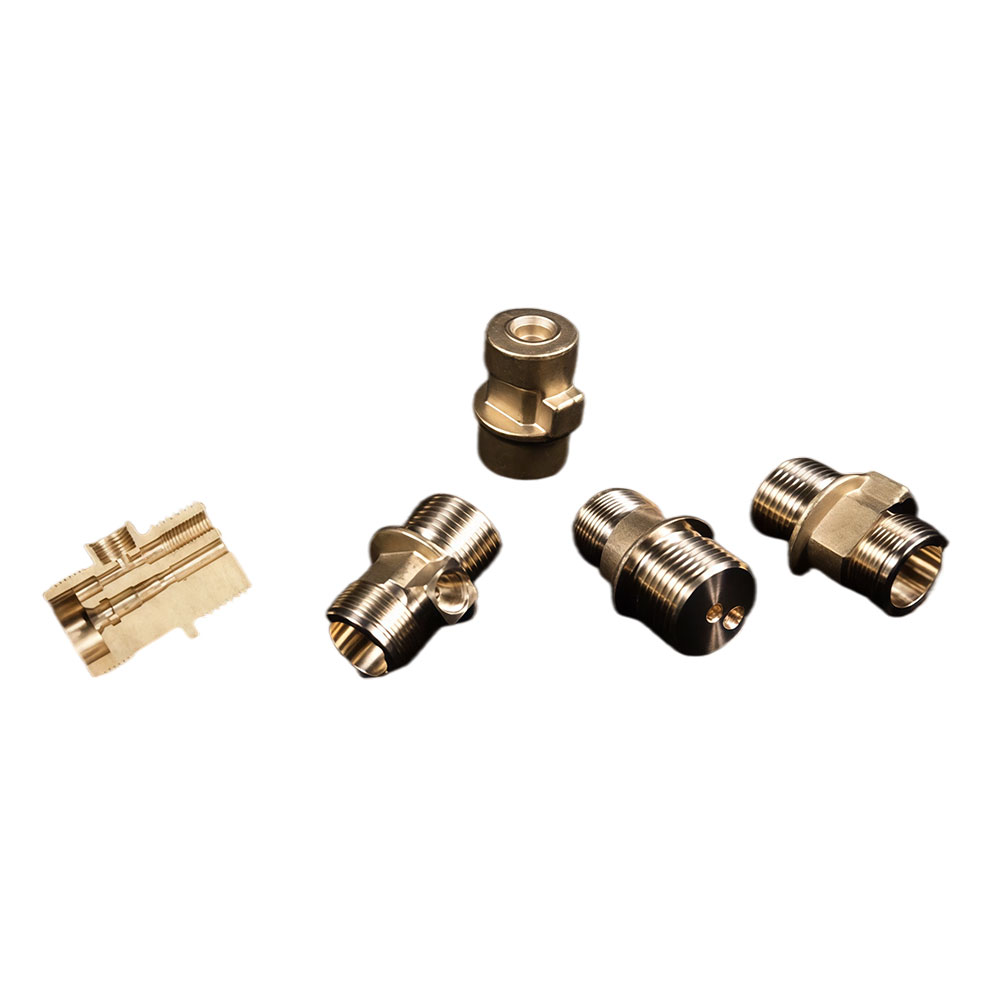
Gate valves feature angled wedge seats and complex sealing faces. These geometries challenge standard machining centers. A Gate Valve Rotary Transfer Machine processes these complex angles efficiently. You must evaluate multi-axis trunnion units within the individual stations. They handle angled cuts smoothly without requiring manual re-clamping. This guarantees perfect wedge seating every single time. It also prevents leaks during final hydro-testing.
Long, deep-bore valves require specific horizontal architectures. A Horizontal Valve Rotary Transfer Machine offers superior chip evacuation. Gravity helps clear heavy metal chips naturally from deep bores. Evaluate spindle rigidity carefully when configuring these systems. Assess bar-feeding capabilities versus cast-blank robotic loading. Bar-fed systems suit continuous long runs perfectly. Cast-blank loading fits custom pre-forged shapes better.
Manifolds introduce multiple intersecting cross-holes into the equation. Tight-tolerance porting remains notoriously difficult here. A Manifold Rotary Transfer Machine solves this precise manufacturing challenge. It addresses intersecting bores simultaneously across multiple stations. You should assess the need for specialized automatic deburring stations. High tool-capacity indexing heads are also critical. They allow rapid internal tool changes for generating complex port profiles seamlessly.
Machine Configuration | Ideal Valve Type | Key Engineering Advantage | Primary Material Form |
|---|---|---|---|
Vertical Trunnion Style | Gate Valves, Ball Valves | Angled multi-axis processing | Castings, Forgings |
Horizontal Spindle Style | Deep Bore, Spool Valves | Superior gravity chip evacuation | Bar Stock, Long Forgings |
High-Capacity Indexing | Hydraulic Manifolds | Handles multiple intersecting holes | Block Blanks, Extrusions |
Changeover times limit production flexibility. Mechanical changeovers sometimes take several hours or even days. You must acknowledge this downside transparently. Low-volume or high-mix batches suffer severely here. A standard CNC multi-sensor machine often beats transfer systems for short runs. Determine your exact production threshold before committing capital. If you run batches smaller than fifty thousand units annually, reconsider your strategy. Dedicate these transfer machines to long, uninterrupted production runs.
Material variables dictate your cutting strategies. Forged brass cuts easily but requires extremely fast chip clearing. Cast iron introduces abrasive wear on expensive tools. You must manage tool life aggressively to maintain profit margins. 316 stainless steel valve bodies work-harden quickly as you cut them. They demand highly rigid spindles and specialized carbide inserts. Adjust your feeds and speeds based on specific material metallurgy. Do not assume one cutting parameter fits all alloys.
Integrate robust in-process metrology into your workflow. You need in-line gauging stations to catch dimensional errors early. Air gauges and touch probes work exceptionally well here. They detect microscopic tool wear before tolerance limits are breached. This prevents bad parts from moving downstream to assembly. Automated feedback loops adjust tool offsets dynamically. This creates a self-correcting machining environment.
Common Mistakes in Implementation:
Ignoring thermal expansion during continuous 24/7 production cycles.
Failing to specify high-pressure through-spindle coolant for deep bores.
Underestimating the time required for mechanical fixture changeovers.
Using generic cutting tools instead of application-specific custom tooling.
Define the Factory Acceptance Testing (FAT) protocol rigorously. Do not accept a simple 50-piece sample run from the manufacturer. Demand minimum Cpk values over a continuous 8-hour production run. This proves real-world thermal stability and mechanical endurance. A proper Valve Machining Rotary Transfer Machine must run flawlessly under stress. Site Acceptance Testing (SAT) should replicate these exact results on your factory floor.
Clarify tooling and fixture ownership early. Vendors often design custom chucks and collets for your specific valve bodies. You must establish who owns these engineering designs. Retaining ownership gives you future manufacturing flexibility. It allows you to source replacement collets from third-party toolmakers. Never lock yourself into a single source for consumable fixtures.
Assess integration and automation capabilities thoroughly. You need seamless connections to downstream systems. Robotic assembly cells increase overall factory throughput. Automated part washing removes residual coolant effectively. API 598 pressure testing lines verify final sealing integrity. Ensure your machine communicates smoothly with these automated systems. Standardized PLC protocols like MTConnect or OPC UA make data integration straightforward.
Rotary transfer systems offer unmatched cycle times and tolerance stability for high-volume valve bodies. However, they require highly disciplined process engineering to succeed. The transition from serial CNC machining to simultaneous processing demands rigorous planning. You must control thermal expansion, manage tool wear dynamically, and execute strict metrology protocols. When properly implemented, these systems eliminate setup variance and lock in crucial geometric tolerances.
Your next steps require precise data gathering. Audit your current part families immediately. Calculate true annual production volumes to confirm they meet the high-volume threshold. Prepare strict Cpk and OEE requirements before initiating vendor RFQs. Demand transparent runoff protocols that prove long-term stability. By following this objective framework, you ensure your equipment investment directly solves your most pressing manufacturing bottlenecks.
A: Modern rotary transfer machines routinely hold concentricity within 5 to 10 microns. True positional accuracy typically falls within 10 microns. Surface finishes can achieve Ra 0.4 or better. However, these results depend heavily on the material. Brass and aluminum yield tighter tolerances than tough 316 stainless steel.
A: Conventional CNCs change over in minutes using standardized zero-point clamping. Rotary transfer machines take significantly longer. Modular CNC rotary stations might take several hours to retool. Cam-driven legacy systems can take days. You must plan for longer production runs to offset these setup times.
A: Yes, but it requires specific loading configurations. Extruded bar stock feeds continuously through automated bar feeders. Casting blanks require robotic arms or gantry loaders for precise part orientation. You must specify your primary raw material so the vendor engineers the correct automatic loading mechanism.
A: Industry standards typically place the minimum threshold around 100,000 parts per year. High initial tooling and fixture costs require massive scale to justify the capital expense. If your volumes remain consistently above this floor, the drastically reduced cycle times generate exceptional returns.


