

Views: 0 Author: Site Editor Publish Time: 2026-09-30 Origin: Site
High-volume production of complex parts often creates severe bottlenecks when relying on sequential CNC machining. Shops constantly struggle to push out thousands of components while maintaining tight tolerances. These traditional methods ultimately hit a hard ceiling on output speed. You simply cannot machine parts fast enough sequentially.
Manufacturers must balance the demand for tighter tolerances alongside the need to drastically reduce cycle times. They also need to lower the cost-per-part on runs exceeding hundreds of thousands of units. Falling behind on these metrics directly erodes profit margins. Competitors utilizing faster technologies will easily capture market share.
Shifting from sequential processing to simultaneous multi-station machining fundamentally alters production economics. You achieve unprecedented throughput. This transition makes sense provided the application justifies the initial capital expenditure. In this guide, we explore how these advanced systems operate and scale.
A **Rotary Transfer Machine** executes simultaneous operations across multiple stations, reducing cycle times to mere seconds.
Selecting between a **Horizontal Rotary Transfer Machine** and a **Vertical Rotary Transfer Machine** depends strictly on part geometry, footprint constraints, and chip evacuation requirements.
The technology is optimally deployed for complex, multi-axis components like fluid control systems, making specialized setups like a **Manifold Rotary Transfer Machine** highly viable for continuous production.
Justifying the investment requires rigorous evaluation of minimum production volumes, tooling changeover times, and long-term part consistency.
The central indexing table forms the absolute core of these machining systems. This indexing core securely clamps the workpiece into a dedicated fixture. The table then rotates precisely between customized machining stations. Each station houses dedicated spindles to perform a specific cutting action. Precision servo motors drive this rotation to ensure exact alignment.
We must contrast traditional CNC setups against rotary transfer models to understand the efficiency gain. Traditional CNC relies on sequential processing. It engages one tool at a time. The spindle finishes one feature, swaps tools, and begins the next. Rotary transfer engages all tools simultaneously on different parts. Every single station cuts metal at the exact same moment.
Cycle time calculation changes entirely under this simultaneous model. The "longest operation rule" dictates output speed. Total cycle time equals only the single longest machining operation on the dial.
Consider this standard calculation sequence:
Identify the station taking the maximum time to complete its cut.
Add the index time required to rotate the table to the next position.
The sum equals your finalized cycle time.
If deep-hole drilling takes eight seconds and indexing takes one second, a finished part drops every nine seconds. The other shorter operations simply wait for the index.
Holding the part in a single fixture throughout the entire multi-station process guarantees superior tolerance control. The machine eliminates cumulative repositioning errors. Traditional routing often requires moving parts between different lathes or mills. Each handling step introduces tiny misalignments. A single-clamping method maintains perfect dimensional integrity across complex features.
Selecting the right machine architecture determines your overall production success. A Horizontal Rotary Transfer Machine excels at handling longer cylindrical parts. Gravity naturally assists chip evacuation in this orientation. Metal shavings fall directly into the conveyor below. Operators also gain easier access for heavy tooling maintenance. Spindles sit at an accessible height. However, these systems present clear limitations regarding space. They demand a significantly larger factory floor footprint.
Alternatively, a Vertical Rotary Transfer Machine offers distinct spatial advantages. These units feature a highly compact footprint. They suit heavier, block-like parts beautifully. You can easily integrate vertical models alongside overhead gantry loading systems. Gravity feed automation works perfectly here. Chip management stands out as the primary limitation. You must implement highly sophisticated coolant flushing systems to prevent chip buildup inside the lower stations.
We use a structured criteria set to evaluate these orientations. Floor space and part geometry normally dictate the final engineering choice.
Decision Criteria Matrix for Orientation Selection
Evaluation Criteria | Horizontal Architecture | Vertical Architecture |
|---|---|---|
Ideal Part Geometry | Longer, cylindrical shafts | Heavy, block-like components |
Factory Floor Space | Requires substantial footprint | Highly compact, saves space |
Chip Evacuation | Excellent (gravity-assisted) | Requires high-pressure coolant flush |
Loading Automation | Horizontal bar feeders | Overhead gantry robotics |
Common mistakes occur when buyers ignore chip evacuation requirements on vertical models. Packed chips quickly destroy expensive tooling. Always prioritize high-pressure coolant systems if you choose a vertical setup.
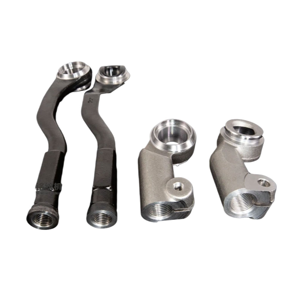
Fluid control components demand rigorous precision and complex multi-axis cutting. A Valve Body Rotary Transfer Machine acts as the indisputable industry standard here. Valve bodies require simultaneous boring, threading, and facing operations. Multiple spindles engage the casting from different angles simultaneously. This process guarantees perfect concentricity between the valve seats and stem holes.
Hydraulic blocks present another profound manufacturing challenge. Manifolds feature intricate intersecting cross-holes. Conventional machining requires multiple setups to hit every face. A specialized Manifold Rotary Transfer Machine handles these challenges effortlessly. It manages deep-hole drilling without requiring any secondary setups. You machine all six sides of a block in one continuous cycle.
Material flexibility requires careful station design. Different metals demand unique cutting strategies. Machining brass allows exceptionally high spindle speeds. Brass chips break easily. Aluminum behaves similarly but requires aggressive chip control to prevent galling. Cast iron demands robust station design. The inherent hardness of iron requires rigid spindles and slower speeds. You must engineer your cutting parameters specifically for the targeted material.
Utilize custom form tools to combine multiple chamfers into one plunge.
Implement tool breakage sensors on deep-hole drilling stations.
Use through-spindle coolant to flush intersecting cross-holes effectively.
Profitability relies entirely on scale when discussing these advanced systems. We must candidly define the volume thresholds. A rotary transfer machine typically becomes highly profitable when production numbers exceed 100,000 parts per year. At this volume, the rapid cycle time generates massive revenue. Below this threshold, a standard 5-axis CNC provides a much safer bet. Smaller runs cannot absorb the heavy initial setup costs.
Changeover realities have historically plagued these machines. Mechanical dial machines once took days to retool. Modern CNC-controlled rotary transfer machines mitigate this issue significantly. They utilize modular tool heads and quick-change collets. Operators load new programs instantly. Still, you must acknowledge changeover remains a real factor. High-mix, low-volume shops often struggle to justify the downtime between jobs.
You must implement strict risk mitigation strategies. Standardize your part designs across your organization. Maximize the machine's lifecycle by using common thread sizes and bore diameters across different product generations. Small design tweaks save massive retooling costs later. Designing parts specifically for multi-station processing ensures long-term profitability.
Buying advanced manufacturing equipment requires rigorous technical validation. You must define strict success metrics before signing a purchase order. Demand guaranteed cycle time run-offs. The builder must prove the machine hits the targeted seconds-per-part under real conditions. Furthermore, require capability index (Cpk) validation. A Cpk score above 1.33 proves the machine holds dimensional tolerances consistently across thousands of cycles.
Automation readiness determines your future scalability. Evaluate integration capabilities deeply. Ask how easily the machine accepts automated bar feeders. Test robotic vision systems for raw casting alignment. Plan for automated pallet unloaders to handle the massive output. A machine lacking automation interfaces quickly becomes a dangerous bottleneck.
Service and support Service Level Agreements (SLAs) keep your lines running. Emphasize the vital importance of localized technical support. You cannot wait weeks for international technicians. Check spare parts availability carefully. Define spindle rebuild turnaround times in writing. Machine downtime halts an entire production line immediately. Your integrator must provide guaranteed rapid response protocols.
Transitioning to multi-station rotary transfer machining represents a strategic move to dominate high-volume precision markets. You completely eliminate the inherent bottlenecks found in sequential CNC processing. Relying on simultaneous cutting slashes cycle times drastically. The initial capital expense pays dividends rapidly when applied to appropriate volume thresholds.
You must rigorously evaluate your part geometries before selecting a horizontal or vertical orientation. Proper chip management and automation integration ensure uninterrupted production. Conduct a thorough cycle-time analysis today. Review your entire part family with a qualified machine builder to validate both technical and financial feasibility. Taking these steps secures your competitive edge in high-volume manufacturing.
A: Cycle times depend strictly on the longest single operation. In most industrial applications, a completed part drops every 2 to 15 seconds. The machine executes all other shorter operations simultaneously within that timeframe.
A: Generally no. They are fundamentally designed for low-mix, high-volume efficiency. While modern CNC-equipped models offer improved flexibility and faster changeovers, frequent retooling destroys the economic advantage. Standard CNC mills fit low-volume work better.
A: These terms overlap frequently. However, a dial machine often refers to lighter assembly or light-machining indexing tables. Rotary transfer specifically refers to heavier, precision metal-cutting applications utilizing highly modular tool heads and high-horsepower spindles.
A: Vertical models rely heavily on high-pressure coolant systems. You flush coolant aggressively through the tooling and across the fixtures. Strategic base designs utilize steep internal angles to prevent chip packing in the lower stations.


